2019年3月2日 星期六

[micropython] pyboard Drum

從朋友那拿到一組電玩用的鼓組,原本的電路板壞了,朋友自己焊了一塊,轉接到PS搖桿再連到電腦上玩

由於想增加第八個鼓面,朋友原先的電路感覺不容易新增與維護
於是選擇了用 pyboard 去做改接 (可以直接模擬成電腦搖桿的 Arduino 板不知丟哪去了 Q_Q)
每個鼓面下面都是蜂鳴片(壓電元件),並上 1M ohm 電阻後,
一端接地,一端接 AD輸入[1][2][3]

pyboard 提供了可以當成電腦鍵盤的功能 (接上USB時,電腦辨識成鍵盤)
當成電腦鍵盤時,同時可模擬按壓六個按鍵 [4][5]

pyboard 的USB連接到電腦時,可以是 [6]
互動執行 + 隨身碟(儲存裝置) 或
互動執行 + HID裝置 (可以為滑鼠或鍵盤)

隨身碟模式方便把寫好的程式拷到板子上跑,HID鍵盤裝置是最終要玩打鼓遊戲的設置

一開始先測試 pyboard 的 AD [7] 
先連續讀值並把數值丟出來看(如下),冒號右邊為保值的最大值
   37    22    25    24    30    28    27    20 : 49 1179 120  40  42  62  46  30
   34    23    27    22    27    32    23    13 : 49 1179 120  40  42  62  46  30
   35    24    24    22    28    25    20    15 : 49 1179 120  40  42  62  46  30
上面分別為八個鼓面的 AD輸出與最大值的保值
多試個幾次去記錄最大值,以此值做 閥值的參考
當讀值超過閥值時,才當成有輸入

測試過程中可以發現透過鼓架傳遞震動,有時敲 A 鼓,B也有反應,但輸出較小,持續時間也較短
於是加入第二個判斷,當超過閥值時,計數陣列值+1
如下為 3 與 4 鼓面同時被判定有輸入,持續時間達 7 ms 與 2ms (使用每 1ms 讀一批次AD)
[0, 0, 7, 2, 0, 0, 0, 0]

當持續發生有輸入時,送出對應的按鍵值給電腦
電腦對按鍵的辨識,間距要 10ms 以上,不然會出錯

以下程式,其中 main 裡面放了
changetMode() 方便切換 Storage 與 HID
modify_threshold() 方便修改閥值(在HID模式時)並儲存 
ma() 使用前要關掉 timer 中斷( tim2.deinit());用來查看連續的AD讀值

boot.py

# boot.py -- run on boot-up
# can run arbitrary Python, but best to keep it minimal

import machine
import pyb
#pyb.main('main.py') # main script to run after this one
#pyb.usb_mode('VCP+MSC') # act as a serial and a storage device
#pyb.usb_mode('VCP+HID') # act as a serial device and a mouse
pyb.usb_mode('CDC+HID',hid=pyb.hid_keyboard)

main.py

#hardware platform: pyboard V1.1
import time
import os
import struct
import micropython
import machine
import pyb

def changetMode(m='f'):
 '''
 parameter mode
 m = 'f' : flash
 m = other: HID_KB
 '''
 # from HID_KB mode return to Flash mode
 f=open('boot.py', 'r')
 boot=f.readlines()
 f.close()
 if m == 'f' and len(boot)>8:   # USB to flash mode
  print('back to flash mode, will reset')
  boot.pop(-1) 
  f=open('boot.py', 'w')
  for i in range(len(boot)):
   f.write(boot[i])
  f.close()
  machine.reset()
 else:          # USB to HID KB mode
  print('change to KB mode')
  f=open('boot.py', 'w')
  for i in range(len(boot)):
   f.write(boot[i])
  f.write(b"pyb.usb_mode('CDC+HID',hid=pyb.hid_keyboard)")
  f.write('\n')
  f.close()
  machine.reset()

  
hid=pyb.USB_HID()

# byte 0 Modifier keys
# byte 1 Reserved
# byte 2 Keycode 1
# byte 3 Keycode 2
# byte 4 Keycode 3
# byte 5 Keycode 4
# byte 6 Keycode 5
# byte 7 Keycode 6
# max 6 keys send at the same time 


def release_key():
 global hid
 buf = bytearray(8) # report is 8 bytes 
 #buf[2] = 0
 hid.send(buf) # key released
 pyb.delay(10) #must delay 10ms

def press_key(key = [0]):
 global hid
 buf = bytearray(8) # report is 8 bytes 
 for i in range(len(key)):
  buf[i+2] = key[i]
 #buf[i+3] = 40 # Enter; for Note test
 hid.send(buf) # key released
 pyb.delay(10) #must delay 10ms


X1 = pyb.ADC(pyb.Pin('X1')) # set X1 for analog input 
X2 = pyb.ADC(pyb.Pin('X2')) # set X2 for analog input 
X3 = pyb.ADC(pyb.Pin('X3')) # set X3 for analog input 
X4 = pyb.ADC(pyb.Pin('X4')) # set X4 for analog input 
X5 = pyb.ADC(pyb.Pin('X5')) # set X5 for analog input 
X6 = pyb.ADC(pyb.Pin('X6')) # set X6 for analog input 
X7 = pyb.ADC(pyb.Pin('X7')) # set X7 for analog input 
X8 = pyb.ADC(pyb.Pin('X8')) # set X8 for analog input 

AD = [X1, X2, X3, X4, X5, X6, X7, X8]

KBKEY = [30, 31, 32, 33, 34, 35, 36, 37] # mapping HID KB 1 ~ 8

# Timer 1 ~ 14
#Timer 3 is reserved for internal use, and 5 and 6 are used for servo and ADC/DAC control

import threshold as th

threshold = th.threshold

DRUM = [0]*8 # 
AVG = [0]*8 # for average
ADV=[0]*8 # store read AD value
flg20ms = 0

hisstat=[0]*8 # history of DRUM status

# if DRUM 0 -> 1, do nothing
# if DRUM 1 -> 0, set 1 (button up trigger)
flg_doeven = 0

def Timer2callback(t):
 global AD
 global ADV
 global DRUM
 global threshold
 global hisstat
 global flg_doeven
 global flg20ms

 if flg20ms > 0:
  flg20ms = flg20ms - 1
  
 for i in range(8):
  ADV[i] = AD[i].read()
  
  if ADV[i] > threshold[i]:
   DRUM[i] = 1
   hisstat[i] += 1
  else:
   DRUM[i] = 0
   if hisstat[i] > 2:
    if flg20ms == 0:
     print(hisstat)
     flg20ms = 20
     flg_doeven = 1

def modify_threshold(threshold):
 f = open('threshold.py', 'w')
 f.write('threshold = [')
 for i in threshold:
  f.write(str(i))
  f.write(', ')
 f.write(']')
 f.close()

def ma(op = 0):
 global AVG
 global ADV
 global DRUM
 MAXV = [0]*8
 while(1):
  AVG = [0]*8
  for j in range(20):
   for i in range(8):
    ADV[i] = AD[i].read()
    AVG[i] += ADV[i]
  for i in range(8):
   AVG[i] //= 20
   if AVG[i] > MAXV[i]:
    MAXV[i] = round(AVG[i])
  
  if op == 0:
   print('{:>4} {:>4} {:>4} {:>4} {:>4} {:>4} {:>4} {:>4}'.format(ADV[0], ADV[1], ADV[2], ADV[3], ADV[4], ADV[5], ADV[6], ADV[7]))
  elif op == 1:
   print('{:>4} {:>4} {:>4} {:>4} {:>4} {:>4} {:>4} {:>4}'.format(DRUM[0], DRUM[1], DRUM[2], DRUM[3], DRUM[4], DRUM[5], DRUM[6], DRUM[7]))
  else:
   for i in range(8):
    print('{:>5} '.format(round(AVG[i])), end='')
   print(':', end='')
   for i in range(8):
    print('{:>3} '.format(MAXV[i]), end='')
   print()

tim2 = pyb.Timer(2, freq=1000)
tim2.callback(Timer2callback)
#tim2 = pyb.Timer(2, freq=1000, callback=Timer2callback) # 1ms
flg_release = 0

while True:
 if flg_doeven == 1:
  PK=[]
  for i in range(8):
   if hisstat[i] > 3:
    PK.append(KBKEY[i]) 
  for i in range(8):
   hisstat[i] = 0
  press_key(PK)
  flg_doeven = 0
  flg_release = 1
 else:
  if flg_release == 1:
   flg_release = 0
   release_key() 
 pyb.delay(10)

threshold.py

threshold = [700, 1700, 1500, 1800, 650, 350, 400, 130]

參考:
[1] 极客DIY:利用Arduino制作电子鼓 https://www.freebuf.com/news/topnews/60389.html

[2] Arduino Leonardo/Micro As Game Controller/Joystick  https://www.instructables.com/id/Arduino-LeonardoMicro-as-Game-ControllerJoystick/

[3] [ Arduino ] Arduino電子鼓 – Arduino Drum using Hairless MIDI + pizeo disk https://yoyotechnology.wordpress.com/2015/07/15/arduino-arduino%E9%9B%BB%E5%AD%90%E9%BC%93-arduino-drum-using-hairless-midi-pizeo-disk/

[4] 什麼是 N-key 與按鍵衝突?原理說明、改善技術、選購注意完全解析https://www.techbang.com/posts/10235-keyboard-triggers-do-not-bomb-almighty-from-the-matrix-to-the-circuit-n-key-conflict-with-the-keys-in-the-end-is-what-computer-king-75-fully-understood?page=4

[5] 【micropython】用python來進行BadUSB的USB-HID測試(含無線控制) https://codertw.com/ios/58229/

[6] http://docs.micropython.org/en/latest/library/pyb.html?highlight=usb_mode#pyb.usb_mode

[7]  ADC performance of MicroPython boards https://forum.micropython.org/viewtopic.php?t=2682

注意:
1. timer 中斷裡不能使用浮點數除法,若要做移動平均,要用 // 做整數除法
2. 雖然有 14 個 timer (1~ 14),但是系統用的 (3, 5, 6)
    要避開 http://docs.micropython.org/en/v1.9.4/pyboard/pyboard/tutorial/timer.html?highlight=timer


2018年12月13日 星期四

Python re 模組 (備忘)


功能太多,每次要用都要重學的模組

要找保留字的話,前面要加  \ 符號

 .   代替任何字元

 *  重複此符號前面的項目零次或多次
     項目可為 [] 所指定的內容,或是 

 +   重複此符號前面的項目至少一次,至多次
      譬如找數字  [0-9]+ 找一個以上的數字串
     也可用 \d+ 來實現

[...]  搜尋 [] 內指定的字元,譬如只找數字 [0-9] ,只找英文字[a-zA-Z],只找小寫字母[a-z]

(?#...)  在本已複雜難懂的正則表達式中加註釋,使字串更難以閱讀 (?#....) 中的內容會被忽略

 (?<=....)   找尋字串的開頭須符合 括號內指定的項目  
          
 (?=....)     找尋字串的結尾須符合 括號內指定的項目  

 (?!....)     找尋字串的結尾不包含 括號內指定的項目  


re.compile(pattern[, flags])

re.search(pattern, string[, flags])


譬如 telnet 有控制碼 '\x1b[...;...m' 做前景被景顏色控制
可用pattern  '\x1b\[[0-9;]*m' 來找出有關顏色控制的字串
若無,則回傳 None

a = re.search('\x1b\[[0-9;]*m', receivedata)
# 由於 [ 為保留字,要找保留字符時,前面要加 \
# 數值與 ; 有可能出現多次,故使用 * 來表達*前面的項目要重複找
if a != None:
    control_code = receivedata[a.start():a.end()]  # 取出控制碼


2018年6月18日 星期一

Micropython on ESP8266 (windows)


前幾天看到有人介紹 MicroPython on esp8266,於是翻找出2015年時買的 NodeMCU WiFi板來試看看

Micro python 介紹 http://docs.micropython.org/en/latest/esp8266/index.html

以下包含:
 Windows環境中安裝 micropython 到 esp8266
 設定 repl
 連接 OLED (使用SPI 介面)   
         I2C 請參考 https://medium.com/@rovai/micropython-on-esp-using-jupyter-6f366ff5ed9
 顯示文字到 OLED

1. 安裝 esptool 
    命令提示字元下輸入
 pip install esptool

  安裝完後,建議將 C:\Python36-32\Lib\site-packages\ 下的 esptool.py 拷貝到其他目錄
  e.g: d:\esp8266\


2. 接上裝置,查看電腦偵測到的串列通訊連接埠(com)是多少
   清除flash
    python esptool.py --port com3 --baud 19200 erase_flash
下載image (  http://micropython.org/download#esp8266   )
 下面用 esp8266-20180511-v1.9.4.bin 舉例
   python esptool.py --port com3 --baud 460800 write_flash --flash_size=detect 0 esp8266-20180511-v1.9.4.bin


3.開啟 putty (或其他可用com串列通訊的程式)
    使用 115200 bps 通訊速度
 按 [Enter] 後可以看到提示字元


4. 設定 webrepl (可以使用網頁方式操作repl)
 先設定後可以使用網頁方式連線 webrepl
    在TTY 下設定使用 webrepl
    import webrepl_setup
reboot後,要重新插拔裝置,再連線

5. 設定 WiFi 連區網
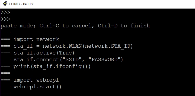
 TTY中按 Ctrl + E 可以用黏貼模式直接貼一整段 code,貼完後按 Ctrl + D 結束
import network
sta_if = network.WLAN(network.STA_IF)
sta_if.active(True)
sta_if.connect("SSID", "PASSWORD")
print(sta_if.ifconfig())
import webrepl
webrepl.start()
SSID, PASSWORD 請自行換成所用的區網訊息

 按 Ctrl + D 後會執行剛才輸入的程式,如下:(IP會有所不同,看區網設定)
預設會打開 AP mode (192.168.4.1)
 可以搜尋 wifi 訊號,找到 MicroPython-xxxxxx  (每個裝置會有不同的號碼)
 或使用前面資料開啟的 STA mode

6. 使用webrepl 連線
  http://micropython.org/webrepl/
如果是連線到esp8266 的AP,可以直接按 Connect 做連線
 若是連到自己的區網,後面網址需修改為步驟 5 時得到的 IP 
 WebREPL連線時,會要求 步驟4 設定的密碼
(上面是連線後按了多次 [Enter])

7. 下載 boot.py 程式做修改
    網頁 WebREPL 畫面的最右邊或最下方,有操作介面
 可以 直接上傳本機電腦中檔案 或 下載ESP8266中的檔案
 下載 boot.py


   注意:瀏覽器可能會警告下載 .py 類型的檔案

8. 修改 boot.py 檔案後再上傳
 將網路設定寫到 boot.py 中,這樣之後 reboot ,就能直接用 webrepl 連線

9. 下載 OLED driver
 可以在 https://github.com/micropython/micropython 下載驅動
 以下將使用 https://github.com/micropython/micropython/blob/master/drivers/display/ssd1306.py
 透過 網頁 WebREPL 將 ssd1306.py 下載到 ESP8266 中

10. 連接 OLED with SPI
 (2014買的OLED,板子預設是使用 SPI 介面)


11. 寫 OLED init 程式
from machine import SPI
from machine import Pin
import ssd1306
dc_pin = Pin(5, Pin.OUT)
cs_pin = Pin(15, Pin.OUT)
res_pin = Pin(4, Pin.OUT)

spi = SPI(baudrate = 100000, sck=Pin(14), mosi=Pin(13), miso=Pin(12))
#class SSD1306_SPI(self, width, height, spi, dc, res, cs, external_vcc=False):

oled = ssd1306.SSD1306_SPI(128, 64, spi, Pin(5), Pin(4), Pin(15))
oled.init_display()
oled.fill(0)
oled.text('test', 0 ,0)
oled.show()
將程式命名後上傳到 ESP8266 中,即可使用 import XXXX.py 後執行


12. 後記
 SPI 挺浪費有限的 GPIO,現今買的 OLED 預設多為 I2C 介面,只需兩隻接腳。
 可以將連線的 IP 顯示在 OLED 上,就可以都用 WiFi 做連線控制。
 網路上有神人做 WiFi 跑 MQTT;可以一對多控制,需要再花時間研究。
 還沒測試 IRQ,這個應該是單晶片機上比較需要的功能。
P.S:
   1. 注意 .py程式的縮排,不支援 TAB,需使用 SPACE. 
   2. 原先 NodeMCU系統重新配置的 IO 腳位是印在電路板上,在 MicroPython 使用的是晶片原始的 GPIO,要參考原始的配置,而不是看電路板上標明的值。
3. https://forum.micropython.org/viewtopic.php?t=2440
        RTC的使用方法
  import ntptime
  rtc = machine.RTC()
  ntptime.settime() # update time form internet
  print(str(rtc.datetime())

#Timer 使用參考 https://www.dfrobot.com/blog-606.html

2015年10月3日 星期六

NodeMCU 從網上取得時間

基於 : http://softbugbug.blogspot.com/2015/10/python.html

要有全域變數 HH, MM, SS
timer 要數時間
此段程式碼功能為 連上網路更新 HH, MM, SS 的數值

-- ['gettime.lua'] 
-- get time from web
-- update NodeMCU time base on get from web  
url = "http://time.artjoey.com/js/basetime.php"
site = "time.artjoey.com"
loc = "/js/basetime.php"

data = "GET "
  ..loc.." HTTP/1.1\r\nHost: "
  ..site.."\r\nConnection: keep-alive\r\nAccept: */*\r\n\r\n"

sk=net.createConnection(net.TCP, 0)

sk:on("receive", function(sck, c) 
  print("receive") 
  print(c)

  get={string.find(c,"baseTime=")}
  --If GET value exist,
  if get[2] ~= nil then 
    print("P:")
    print(get[2] )   -- print the start location of serch string 
    basetime = string.sub(c, get[2]+1, -7)   -- last char are 000;CrLf.  get basetime
-- example basetime = 1443789637
--  NodeMCU max value 2147483647 
    print(basetime)
    print("before:"..HH..":"..MM..":"..SS)
    esp_update() 
    print("after:"..HH..":"..MM..":"..SS)
  end

end )
sk:on("disconnection", function(sck, c) 
  print("disconnection")
  print(c)
end )
sk:on("connection", function(sck, c) 
  print("connection") 
  print(c)
end )

sk:connect(80,ip)
sk:send(data)

function esp_update() 
  twsec = basetime + 28800  -- 60 * 60 * 8  add 8Hr (tw: GMT + 8)
  daysec = twsec % 86400    -- 60 * 60 * 24
  HH = daysec / 3600        -- 60 * 60
  MM = (daysec / 60) % 60    
  SS = daysec % 60
--  webs()                  -- run http_server after update time
end

題外話:
NodeMCU 的字串連接式為 ..
ex: 
 str1 = "Hellow"
 str2 = str1..123     -- 數值型態的資料在此會自動轉為字串
 print(str2)
 Hellow123

Python 從網路上取得時間

做 client 端的應用時, 想要從網路上取得時間
NTP(網路時間協議) 的取得比較複雜
基於沒有要使用很精準的時間,於是把目標放到找一個有顯示時間的網頁就好了
且網頁內容要簡單,以免 client 端下載時系統資源不敷使用

在google 上找到一個 台灣時間  網頁
用 chrome 的開發人員工具
看到在 id = local_time 的後面有包含時間,這段在紅框標示處
於是把網址(底下橘色畫線)處改為紅框處的內容
http://time.artjoey.com/js/local.htm
到這邊,需要下載的網頁內容已經減少許多
使用 python 抓取網頁
發現在 id = local_time 後面的資料內容是 Clock...
這不是我們要的東西,於是再找網頁內容
在 <head> 中有一段
將紅框中的網址取代上面橙色底線,得到 http://time.artjoey.com/js/basetime.php 

至此,可以看到一個很熟悉的數值 1443....
才怪
此例中的 baseTime 為 從1970/01/01 開始到現在的毫秒數
所以把數值取出來後,先除 1000 換算成秒

以下是一小段 python 程式,演示取出當日時間

# 使用網路資源
import requests
import urllib

url = "http://time.artjoey.com/js/basetime.php"
res = requests.get(url)
# res.content type is <byte>
basetime = res.content.decode('ascii')
# var baseTime=1443757229000;
ms = int(basetime.split('=')[1][:-1])   # 用'='分隔, 取出第二組字串的 開頭到倒數第二字元 (最後字元是分號)
twsec = ms / 1000 + (60 * 60 * 8) # 台灣是 GMT + 8, 要把偏差的秒數加上去
daysec = twsec % (60 * 60 * 24)   # 僅取出當日開始到目前的秒數
HH = int(daysec / 60 / 60)
MM = int(daysec / 60) % 60
SS = int(daysec % 60)
print(HH,MM,SS)


2015年10月1日 星期四

NodeMCU (ESP8266) 使用紀錄(暫存)

最近入手了塊 WiFi 小板子,使用 ESP8266 模組
NodeMCU官網 紹所描述的如下圖所示,使用方法 超簡單!!!
就如惡夢的開端一樣平凡

===寫在前面===
建議:
1沒有任何程式基礎的別玩這模組,最好有網頁編寫能力(前台 (HTML, JAVAScript)/後台 (Node.js) 都要)
2這模組還算新,各種支援/資源都很欠缺;現有的開發工具很難使用,操作上需要耐心
==========
模塊大小示意
左邊為 50元新台幣 右邊為 1元人民幣

硬體程式更新 
 在板子買來時,應該都預裝了較舊的系統,可以下載較新的來使用
 https://github.com/nodemcu/nodemcu-firmware/releases/tag/0.9.6-dev_20150704
 
 更新程式步驟可以參考 http://bbs.nodemcu.com/t/nodemcu/22 中的
  準備工作
  開始 的 一二步 (第三步用 telnet 進行測試的工作可以先不管)
 
 這一段很重要,必須先學會;因為在後面的操作嘗試過程中,有可能發生因程式錯誤導致模組不斷自我重啟,這時簡單的處理方式就是重新下載硬體程式 (應該也有別的方法,但是沒找到)

軟體操作環境 (NodeMCU Studio 2015)
 在 http://bbs.nodemcu.com/t/nodemcu-studio-ban-ben-geng-xin-wei-build20150111-update-to-version-build20150111/64 下載最新的軟體操作環境
 
 操作環境介紹
   
  共分五個區域 
   紅框-選單 (通常只用來 新增 lua檔案)
   橙色框-對模組進行操作 (下載所選到程式Download 執行所選到程式Execute 模組中的檔案瀏覽Explorer
   綠色框-電腦中的程式列表(此列表為電腦中程式,與模組中的不見得相同)
   藍色框-左邊選到的程式內容會在此區域顯示,可以在這邊做編輯修改,修改後的內容會直接存檔在電腦中
   紫色框-訊息區;像終端機的環境,模塊所返回的訊息會顯示在這邊,也可以直接在這邊下操作命令(注意:這區的操作需要用鍵盤輸入,不可用貼上)

  電腦一開始連接上模組時,訊息區會先跑一段亂碼出來,這沒有辦法避免,之後會顯示硬體程式的版本,若有燒錄了 init.lua 程式,則會自動執行
  
  橙色框的 Explorer ,可打開如下對話框,
  按右邊的 Load 可顯示 NodeMCU 中的檔案,於淡紫色框


硬體介紹
 注意事項寫在前面:
  板子使用 microUSB 5V供電,超過此電壓可能會 
打開異次元通道導致模組損毀
  在ESP8266上面的 GPIO 於 NodeMCU 程式上被重新對應編號,使用時須注意要按照 NodeMCU 的編號來進行操作 
 
 板子所提供的接腳角功能如下圖(左下側方塊表示顏色所對應的 pin 腳功能)
其中 D0 連接板子上的 紅色LED (反向動作,寫 gpio.HIGH 為暗)
   
    10bits ADC  一個
 GPIO     十一個 (除D0外,D1 ~ D10 均可用於 PWM 輸出)
 timer     七個 ( 0 ~ 6 )

程式編輯
 使用的語言是 Lua,不過目前只支援其中一些方法(可能是為了精簡以便在空間很迷你的模塊上實現)

 部分可使用的API介紹 http://bbs.nodemcu.com/t/nodemcu-api/28 (完整的可能須自行到 https://github.com/nodemcu/nodemcu-firmware 下載原始碼來看有加入那些功能)
 
 舉例
 system:
  node.restart() 重啟模塊

  h = node.heap() 返回系統剩餘的程式儲存空間(byte)

 timer:
  tmr.alarm(id, interval, repeat, function do())
  example:
   tmr.alarm(0, 5000, 1, function()
      adv = adc.read(0)    -- read 10bits ad value
   end)
   說明:使用timer0, 每5秒讀取一次ADC的值存放到adv中

 gpio:
  gpio.mode(pin, mode, pullup)
   mode 值:gpio.OUTPUT or gpio.INPUT or gpio.INT(中斷模式)
   pullup 值: gpio.PULLUP or gpio.FLOAT, 預設為 gpio.FLOAT

  gpio.write(pin, mode)
   mode 值: gpio.HIGH or gpio.LOW

  status = gpio.read(pin)
   pin值:0 ~ 11  (D0 ~ D11)

 wifi:
        wifi.setmode(mode)     設定WiFi的使用模式
  可以使用 Station,AP 或 (?) 模式 (wifi.STATION, wifi.SOFTAP, wifi.STATIONAP
  
子模組 wifi.sta:
   wifi.sta.config("ssid","password") 設定連接時要用的 SSID, PASSWORD

   wifi.sta.connect()    透過設定好的 SSID, PASSWORD 連接上AP

   wifi.sta.disconnect()  斷開連接

   ip, nm, gw = wifi.sta.getip()  取得 ip位址,遮罩,預設閘道

  子模組 wifi.ap:
   除 wifi.ap.config 用法要注意引述為 tuple 型別,其他可參考 sta 模塊
    cfg={}
    cfg.ssid="SSID"
    cfg.pwd="password"
    wifi.ap.config(cfg)
  
 net:
  常量 net.TCP, net.UDP
  net.createServer(type, timeout) 創建網頁伺服器. timeout為(sec)

   example:
   sr = net.createServer(net.TCP)  
   sr:listen(80,function(conn)
      conn:on("receive", function(conn, payload) print(payload) end)
      conn:send("hello world")
   end)
  說明:建立網路伺服器, 監聽 prot: 80, 當收到 receive 請求時, 在 訊息區 印出 client 傳來的內容, 並在 client 端網頁上顯示 hello world
 

其他
 HTML 超文件標示語言(英文:HyperText Markup Language,HTML)是為「網頁建立和其它可在網頁瀏覽器中看到的資訊」設計的一種標示語言。
 JavaScript 一種直譯式程式語言,是一種動態型別、基於原型的語言,內建支援類別。它的直譯器被稱為JavaScript引擎,為瀏覽器的一部分,廣泛用於用戶端的腳本語言。
 Node.js 是一個開放原始碼、跨平台的、用於伺服器端和網路應用的執行環境。Node.js應用用JavaScript語言寫成。

 HTTP協議參考:
  http://www.kafan.cn/edu/48002124.html HTTP协议详解
  
 用戶連接網頁時,會送出兩次網頁請求 (當作伺服器的 NodeMCU 於 receive 事件會觸發兩次)

 網頁連接時客戶端會送出請求 要讀取用於網頁抬頭的圖案 favicon.ico , 目前不知道有什麼方法可以下載圖檔到 NodeMCU 中

 一個網頁需要有 HTML HEAD BODY 標記
 
 HTML 中的 input 方法所得的值,會在跟伺服器提出請求時加在資料尾端一起送出(中間隔一空行)

奮戰一周的網頁截圖

2015年8月23日 星期日

Python 學習筆記 - 2 轉換文件編碼 (簡體字 -> UTF-8)

有鑑於上淘寶買的硬體開發板,所附的範例程式都是簡體字編碼,
在繁體中文系統下打開時會顯示成亂碼。
過去是用簡體作業系統打開後另外存成unicode編碼,再拷回繁體系統下使用。
最近嘗試了使用 python 做編碼轉換的動作,以處理亂碼顯示的問題。